Proper design of haul road lighting systems is essential to the efficient and safe operation of an open cut mine writes Nitai Pal, S.Vamsi Krishna and Pradip Kumar Sadhu.
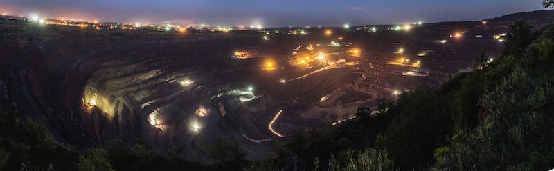
At a surface mine covering many square kilometres of land; where work is carried out round the clock; systematic artificial lighting is necessary in order to provide a safe and efficient working environment.
Haul roads within the pit are one of the most critical areas for lighting at an open cut mine. One of the most important issues is that haul road lighting installations are not permanent due to regular advancement of the working face. [1] Another major problem is dark surroundings and low surface reflectance. Due to these reasons it is very difficult to maintain lighting standards specified by various regulatory bodies. A good lighting system is one which can distribute an appropriate amount of light evenly with uniformity values from 0.25 to 0.40 and with a colour rendering index of at least 60. Good lighting will use energy efficient lamps in suitable luminaries [14]. Mine safety guidelines suggest a minimum horizontal illuminance level of 0.5 lux in haul roads, [2] [4] however in reality uniformity ratio is also essential in the design of illumination systems for uniform distribution of light and to provide sufficient illumination for visual tasks.
In these conditions, the use of compact fluorescent lamps (CFL) with a stand-alone lighting system is perfectly acceptable. Stand-alone photovoltaic lighting systems provide flexibility for changing the location of poles according to changes to surface mine haul roads. However CFL’s electrical requirements are not easily met by hard-switched inverters due to higher switching losses at higher frequencies. The difficulty in meeting the complex electrical requirements, such as preheat and ignition voltage of CFL, results in lower efficiency. In order to make a successful photovoltaic lighting system, the first step is to select a well-suited high-frequency inverter and a series interrupting type charge controller for producing good light while maintaining reliability.
READ RELATED
- Revolutionising the future of High Voltage Coupler Systems
- Ultra Low Voltage Drive for mining equipment
PRINCIPLES OF HAUL ROAD LIGHTING
Seven different types of light pole layouts are possible for haul roads including single sided, double sided opposite, staggered, twin central, a central catenary system, a centrally suspended system [3] [5] and a single sided stand-alone photovoltaic lighting system. Among these, the single sided stand-alone photovoltaic lighting system arrangement is the most prevalent one in mines as installation of poles and electrification process in this layout is simple – no connection is required from one pole to another.
MOUNTING HEIGHT
Luminaire mounting height depends on the lighting arrangement and effective road width. The effective width is the horizontal distance between the luminaire and the far curb. To achieve a good distribution of light across the roadway, mounting height in general is kept equal to the road width or around it.
SPACING
Luminaire or pole spacing for a given lighting arrangement and luminaire light distribution is dependent on the mounting height and the longitudinal uniformity planned for the installation. The greater the mounting height, the larger can be the spacing for a given longitudinal uniformity.
Longitudinal uniformity is the ratio of minimum to maximum illuminance along a line parallel to the road axis through the observer’s position. However, in practice, excellent illumination is considered to be when pole spacing is not more than 8 times the mounting height.
OVERHANG
Poles are generally installed somewhat off-set from the haul road edge (curb) to provide clearance to the vehicle. Luminaire is mounted on the ranging arm to adjust the distance between it and the curb. Sometimes, projection of the luminaire lies inside the road from the curb, which is known as overhang.
The main purpose of overhang is to provide better uniformity of haul road lighting.
INCLINATION
Inclining or tilting the luminaires up from the horizontal is done to increase light coverage across the road width at a given mounting height. However too much tilting will diffuse the light and reduce its distribution along the longitudinal direction of the road. It is recommended that the angle of tilt, with respect to the normal height of mounting, be limited to an absolute maximum of 10°, a top limit of 5° being preferable. In general the angle varies from 10° to 15°.
UNIFORMITY
The even and uniform distribution of light across the area being illuminated is known as uniformity. It is represented on lighting plans by the symbol UO and is a ratio of the minimum illuminance level to the average illuminance level. A UO value of 0.4 or 40% is recommended to ensure that lighting installations do not create dark patches next to lighter patches. The evenness of light distribution is almost always more important than the levels of illumination being achieved by the system.
COLOUR RENDERING
Colour rendering indicates the extent to which a light source is capable of making objects appear their true colour. Colour rendering is determined by the spectral power distribution or spectrum of the light source [15].
The colour rendering ability of lamps is measured on the Colour Rendering Index (CRI) or Ra scale. The scale varies from 0 to 100, where poor colour rendering lamps have lower values while good colour rendering lamps have high values. One hundred is as good as a black body radiator of the same colour temperature.
INDUSTRIAL LIGHTING DESIGN SPECIFICATION AND VALUES
For effective lighting systems the design should reach specifications. Some are given below and the average levels of illuminance for different applications are shown in Table I [15].
- By using highest practical mounting height
- Utilisation of energy efficient lamps
- Lamps with good uniformity values (>= 40%)
- Accurate aiming of luminaire.

“Low electrical consumption makes CFL an ideal choice for solar photovoltaic (SPV) stand-alone lighting system for surface mine haul roads.”
PRESENT SCHEME
A series parallel resonant mode sine wave inverter is incorporated which provides the basic electrical characteristics required by CFL. This provides protection and higher reliability while offering higher inverter efficiency and above all, a fairly constant lumen output throughout the operating DC voltage range by a unique control. [6] [7]
A series interrupting type charge controller makes the SPV system self sufficient for producing light in remote areas while maintaining reliability. [8] It is clear that the protection should be employed, not only for the lamp, but also for battery charging, which is a major component of the system. It should be efficient, reliable and robust enough against possible mal-operation. The block diagram of a typical stand-alone PV lighting system is shown in Fig. 3.
The schematic circuit diagram of a series parallel resonant mode sine wave inverter for operating CFL is depicted in Fig. 4.
There currently exists many designs for driving CFL. However, it is not easy to comply with complex, yet minimal essential needs of a lamp’s electrical parameters to ensure smooth start up and long life while maintaining adequate lumen output. Some relevant electrical parameters of the lamp are listed in Table 1. [12] [13]

It is observed from lamp manufacturers’ instructions that, due to their compact construction, CFLs perform better with a warm start (certain preheat voltage is applied before ignition voltage is applied to lamp). Once turned ON the lamp behaves like a resistive load. The lamp needs constant voltage and hence current to maintain the lumen output during its entire operating range of varying input voltage.
In this article, a charge controller which ensures charging of the battery from PV array, with minimum losses and a series parallel resonant mode high frequency inverter using MCTs, are discussed for operating the CFL. The spacing and number of poles for the given case has not been considered through a mathematical approach because the environment of a haul road is too complex. We suggest that a number of standalone systems can be adjusted as per the working environment of haul roads experimentally.
CHARGE CONTROLLER
Referring to Fig. 3; due to daily variations of solar insolation (incident solar radiation), the energy available from a PV module follows roughly a sine curve which needs to push this energy to the battery with minimal loss, while preventing a possible reverse power flow of energy from battery to PV modules at night.
A typical (30 W) PV module’s parameters are: Vmax – 16.2 V, Imax – 1.85 Amps and Isc – 2.2 Amps.
The V-I characteristics of monocrystalline PV modules are best suited for battery charging, hence a simple ON-OFF control of the charging device is adequate. The schottky type blocking diode, which has a low forward voltage drop, is used in series with the PV array, resulting in lower losses.
BJT is used for the series-interrupting device of the charge controller, whereas MCT (Turn-on time 0.4 | Sec, Turn-off time 1.25 | Sec for an MCT of 500 V) is chosen as the power device for the half bridge series parallel inverter. For the typical system under consideration, the losses in the series interrupting device are I-squared times R, on or less than 0.25 W at peak power point and the series element drop is 0.12 V at peak current. This ensures maximum energy transfer to the battery from the PV array, while preventing an overcharge condition.
When sufficient PV module voltage is developed and exceeds the available predetermined battery voltage, BJT (Tr) starts conducting because it would have received the turn ON command by the control unit, which also makes adequate base-emitter (Vbe) voltage available to Tr. Subsequent current limit is not essential because of the characteristics of the PV module and its load-matching feature to battery charging. As the battery voltage rises to set level, the drive signal to Tr is cut off and charging is stopped. The recharge does not commence immediately, until the battery voltage is sufficiently lower than the overvoltage trip point.
INVERTER FOR LAMP
Referring to Fig. 3; the proposed series parallel resonant mode inverter is operated above resonant frequency. [9] [10] [11] This circuit topology is chosen because of the following advantages:
- symmetrical and sine wave output waveform
- ease of output voltage control by change of inverter frequency
- ZVS (zero voltage switching) operation in above resonance frequency region to reduce switching losses even at a higher switching frequency [5],[6]
- short circuit proof.
From Table 2 it is seen that the lamp needs a certain minimum voltage during preheat (before applying ignition voltage to turn ON), without exceeding a defined time duration for preheat voltage. It also needs a certain minimum ignition voltage and thereafter the burning voltage is determined by the lamp ratings and applied voltage.
OPERATION OF INVERTER
When the switch is turned ON, the input voltage of the series parallel resonant mode sine wave inverter is adjusted so that the output voltage produced is in the order of 130-150 V RMS (maximum limit of preheat voltage). This results in heating of the lamp cathodes equally by selecting the tap on the output transformer Xr.
After a preset time (preheat interval), the switching frequency is brought near resonant frequency to achieve maximum voltage gain for producing ignition voltage across Xr secondary. This turns ON the lamp when the threshold is crossed. After turning ON the lamp voltage, Xr secondary voltage is reduced to the ON state lamp voltage, determined by the power setting of the inverter. This lamp voltage, and hence lamp current, are hereafter kept constant to give constant lumen output by controlling switching frequency against increase / decrease in DC input voltage, which changes as a result of the varying state of charge of the battery.


“It is observed from lamp manufacturers’ instructions that, due to their compact construction, CFLs perform better with a warm start”
PROTECTIONS
The inverter control signals are disabled if the battery voltage reduces below the set level (battery low trip point). However, they are subsequently enabled only when battery voltage sufficiently recovers after a charge, thereby preventing frequent turn OFF/ON.
This is essential to prevent return-ON of the lamp, because the falling battery voltage recovers and follows the discharge curve determined by the new rate of discharge once the discharge current is stopped due to trip.
Simulation of a PV source was conducted from a current limited DC regulated power supply. After turning ON the lamp, the inverter output was intentionally short circuited near lamp terminals for 1 minute and the short circuit was then removed. The lamp started glowing after removal of the short circuit. The DC blocking capacitors CS1 & CS2 ensure that DC component in the inverter is avoided. A sine waveform ensures a compact design of the gap less high frequency transformer and lower losses.

RESULTS
A prototype board was constructed, showing a fairly constant lumen output over varying input voltages. Throughout the experiment the output power of each CFL is assumed to be constant as specified by the manufacturer. As the battery terminal voltage decreases with respect to time of discharge, the lumen output of CFL also decreases. To maintain constant lumen output of CFL, the inverter operating frequency is decreased. As a consequence, the discharge current of the storage battery is increased.
The battery discharge current is measured by a digital DC ammeter and the corresponding battery terminal voltage is measured by a digital DC voltmeter. The AC voltage across CFL is measured by using a CRO. The voltage across CFL is almost constant which offers constant lumen of CFL. Thereafter, the efficiency of the inverter is calculated from experimental data. The experimental results are referred to in Tables 3 and 4.
CONCLUSION
It has to be borne in mind that optimum design achieved by this study is valid only for the chosen illumination standards. In fact the design parameters, i.e. spacing and number of poles, will vary with the change in standards.
Overall the study reveals that the height of mounting haul road lighting is very important to achieve all the required lighting standards at the same time.
Lamp selection should be made mainly based on efficacy and suitability to each situation. A series parallel resonant mode sine wave inverter is well suited for meeting a compact fluorescent lamp’s complex characteristics. To ensure uniform light output throughout the operating voltage range on input DC battery voltage variation from full charge voltage to lower charge limit voltage, inverter frequency will change automatically by voltage to frequency converter, towards the resonant frequency. When the battery is fully charged, the voltage remains at 14.21 V. In this situation, the inverter operates at 70% of resonant current and when the battery is under lower limit voltage, it will operate at 100% of resonant value. The inverter efficiency was found to be above 94% for a 9W CFL.
PROFILES
NITAL PAL
Nitai Pal received his B.Tech. and M.Tech. degrees in Electrical Engineering from University of Calcutta, and a Ph.D. (Engineering) from Jadavpur University, West Bengal, India. He is currently working as an Associate Professor in the Department of Electrical Engineering, Indian School of Mines, Dhanbad, Jharkhand, India.
S.VAMSI KRISHNA
S.Vamsi Krishna completed his B.Tech. degree in Electrical & Electronics Engineering from JNTU, Hyderabad, India in 2008. He is presently pursuing a Ph.D. Programme at the Department of Electrical Engineering, Indian School of Mines, Dhanbad, India. His research interests include power electronics, energy efficient lighting and communication systems for underground and open cast mines.
PRADIP KUMAR SADHU
Pradip Kumar Sadhu received his Bachelor, Post-Graduate and Ph.D.(Engineering) degrees in 1997, 1999 and 2002 respectively in Electrical Eng. from Jadavpur University, West Bengal, India. Currently, he is working as a Professor in Electrical Engineering at the Department of Indian School of Mines, Dhanbad, India. He has a total of 22 years experience in teaching and industry.
References
[1] P. K. Bandhopadhyay., Lighting of Opencast Mines, Proceedings of National Conference on Lighting for 21st Century, Bangalore, 1989.
[2] CMR (Coal Mine Regulations): India, 1957.
[3] CIE (Commission Internationale deL’Eclairage), Guidelines to the Lighting for Opencast Mines, Publication No. 128 (T.C. 5-03), 1998.
[4] BIS (Bureau of Indian Standards), Indian Standard Code of Practice for Lighting of Public Thoroughfares, IS: 1944 (Parts I and II) – 1970, Fourth reprint, April, 1991.
[5] CIE (Commission Internationale de L’Eclairage), Design Methods for Lighting of Roads, Publication No.132, 1999.
[6] T.H. Yu, H.-M. Huang, T. –F. Wu, “Self excited half-bridge series resonant parallel loaded fluorescent lamp electronic ballasts”, in Proc. 1995 IEEE applied power electronics conference and exposition, vol. 2. pp. 657- 664, 1995.
[7] R. L. Steigerwald, “A comparison of half bridge resonant converter topologies” IEEE Transaction on Power Electronics,Vol. PE- 3 , No .2 , p p 174 -182 April 1988.
[8] J.Applehaum, “The quality of load matching in direct coupling Photovoltaic systems”- IEEE transactions on energy conversion, Vol.EC2, No.4, Dec87.
[9] P.K. Sadhu, N. Jana, R.N. Chakrabarti and D.K. Mittra “A Unique Induction Heated Cooking Appliance sRange Using Hybrid Resonant Converter” International Journal of Circuits, Systems and Computers, World Scientific, Volume 14, Number 3, pp. 619-630, June 2005.
[10] N. Pal, Dr. P. K. Sadhu, Dr. R. N.Chakrabarti, “A Comparative Study of HF Mirror Inverter for Induction Cooker through Real-time and PSPICE Simulation” – Journal of Institution of Engineers (I); Vol 86, pp. 268- 274, March 2006.
[11] Dr. P. K. Sadhu, Dr. R. N. Chakrabarti, Mrs. N. L. Nath, Naveen.K. Batchu, Smita Kumari, Kumari Rimjhim, “Analysis of a series resonant superimposed inverter applied to induction heating” – Journal of Institution of Engineers (I); Vol 84, pp. 214-217, March 2004.
[12] FACTS AND TECHNICAL DATA-OSRAM DULUX EL –The electronic lamp” January 1992.
[13] T. Mizuno, “Solid State based tubular fluorescent ballast”- Lighting Research & Tech.., pp. 72-76, 1983.
[14] Po-Yen Chen, Yi-Hua Liu, Yeu-Torng Yau, Hung-Chun Lee, “Development of an Energy Efficient Street Light Driving System”, ICSET 2008.
[15] Alex Dell, Adam C. Gold, John D. Roebker, Daniel R. Schilling, and Douglas G. Frank, “Investigation and Comparison of Light Emission Technologies”, IEEE,Vol.39,pp70- 74,Sep2002.
ACKNOWLEDGMENT
The authors are grateful to the Indian School of Mines, Dhanbad and University Grants Commission (UGC), Bahadurshah Zafar Marg, New Delhi, India for granting financial support under Major Research Project entitled “Development of Hybrid Off-grid Power Supply System for Remote Areas [UGC Project: F. No. 42-152/2013(SR), w.e.f. 01/04/2013]” and are also grateful to the Under Secretary and Joint Secretary of UGC, India for their active co-operation.


Add Comment