Findings from the recent government enquiry into Coal Workers’ Pneumoconiosis in Queensland led to recommendations for reduction in current Occupational Exposure Limits (OEL) for respirable dust. The implementation of effective controls which can reduce dust levels, particularly dust of respirable particulate size of 10 microns (PM10) and below, will significantly reduce these exposure levels. Dry Fog dust suppression uses an agglomeration technique that can provide up to 99% dust suppression efficiency while adding less than 0.1% moisture to the process using only compressed air and water.
The mechanism for suppression of dust using dry fog is especially effective on respirable dust particles at PM10 and below.
Windbreaks are another technique used to prevent wind erosion and particle uptake from material stockpiles. The purpose of this article is to provide a general background on the science and application of these two dust suppression methods.
History and Science of Dry Fog Dust Suppression
In the 1970’s, the technique of dry fog dust suppression was created by Sonic Environmental Systems, Inc., a U.S. based company, for use in industrial dust suppression, humidification and other applications to convey humidified air without the use of a duct. This was accomplished through the special design of a nozzle that atomized water droplets below 10um in size. Original research and testing was undertaken by the University of Sweden and Colorado School of Mines (Schowergerdt, 1976) on the nozzles’ effectiveness to suppress dust revealed that impaction and agglomeration between a dust particle and binding agent such as water will occur if the water droplet is the same size or smaller than the dust particle.
On the contrary, if the water droplet size is much larger than the dust particles (for example 20-300um in size) – then the dust particle (1-15um) will follow the air stream around the water droplet and stay suspended in the air (see Figure 1).
Following this finding, the University of Waterloo in Canada conducted a study on the use of dry fog in various applications utilizing a pneumatic nozzle to create droplet sizes from 30um to 100um inside an electrostatic precipitator. A similar conclusion was reached regarding agglomeration as the Colorado School of Mines, however, it was also determined that a decrease in residence time did not affect the overall efficiency. This was an important factor in determining the effectiveness of the agglomeration pattern of the droplets.
Another consideration in determining the viability of fog as a dust suppressant is its ability to carry a positive charge as shown through lab and field testing of the Sonic nozzle. Studies have also demonstrated that most industrial pollutants acquire an electrostatic charge as they are dispersed into the air. If charged particulate material is exposed to an oppositely charged water fog, there is an increased probability of collision between the particulates and fog droplets. After contact is made, the particulates agglomerate rapidly and fall
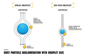
Figure 1: Dust particle agglomeration with droplet size.
out of the atmosphere due to their increased weight. This finding was tested with charged and uncharged fog droplets across a wide variety of industrial pollutants ranging from materials such as coking coal and iron ore crushing dust to other materials that are very lightweight and highly susceptible to moisture such as cement clinker and fly ash (Hoenig, 1977).
The interaction between charged fog droplets and dust particles varied across particulate types but it was noted that the use of fog lowered dust density across all tested materials. For example, when testing dust density of fly ash in a controlled environment, it was found that the fog reduced the density of respirable material by fog by over 91%. There are two factors that attributed to this result. The first is that fly ash dust particles, lightweight and approximately 3um particle size are similar in size to the fog droplet, which facilitates a stronger collision and agglomeration between particles. The second is that the fly ash holds a negative charge which was effectively suppressed by positively charged fog (see Figure 2). The same test with non-charged fog and positively charge foundry dust yielded different results but showed that dust density was still reduced through the agglomeration principal (see Figure 3).
POWER PLANT FLY ASH FLY ASH INJECTED INTO DUST TUNNEL AT 200 °C (392 °f) WATER FLOW 30 ml / MIN.
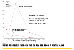
Figure 2: Using positively charged fog on fly ash from a power plant.
Particulate Control
In the above-described results, an air stream was created by which dust particles and atomized water droplets (fog) were able to come into contact and stay in a relatively enclosed space. When this occurs, particle removal from the air stream takes place due to three primary mechanisms:
- Impaction: When the fog droplet flows in the path of the dust-laden air stream, the droplets and dust particles may collide depending on their initial trajectory and velocity. This collision is called impaction (in our case agglomeration). Due to inertia, the impact with the droplet will cause the dust particle to become encapsulated, increasing its weight causing it to fall out of the atmosphere.
- Interception: The finer particles moving within the air stream do not hit the fog droplets directly but rather graze the droplets and adhere to them. This mechanism also causes an increase in particle weight.
- Diffusion: When fog droplets are scattered among dust particles, the particles aredeposited on the droplets by diffusion.
The impaction / interception efficiency increases as the amount of water droplets compared with dust particles increases, the particle size increases (or conversely the water droplet size
MATERIAL, FOUNDRY DUST CONTINUOUS OPERATION FOG WATER FLOW 30 ml / MIN FOG GUN AIR FLOW 100 SCFH DATA CORRECTED FOR WATER PICK-UP ON COLLECTION PLATES
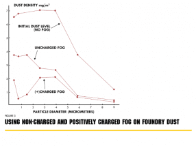
Figure 3: Using non-charged and positively charged fog on foundry dust.
decreases), and the velocity of the droplets is fast enough to create an airstream by which the particles will flow.
It is also important to note in the above study, that as the particle sizes decreased, the surface area of the fog increased. This is easy to understand from a simple physics and calculation perspective. If we have a gallon of water in a simple sphere and split it into 8 smaller spheres the surface area increases, while the volume of water stays the same. Figure 4 demonstrates this concept:
By splitting the droplet into 8 smaller droplets, we have just doubled the size of the surface area. The ultrasonic nozzle creates droplets in the range of 1-10um, with an average droplet size of 5um. We would need to split the spheres 15 times to achieve these sized droplets.
After 15 divisions of the spheres, we will have droplets of average size 5.9um, and a surface area of approximately 3848 meters squared versus the original sphere at 0.12 meters squared. In terms of dust suppression, this means that less water is used to achieve the same suppression by agglomeration. The idea is to overwhelm the dust particles with the fog to create this opportunity for impaction and interception. With more fog and droplets, the chances of agglomeration greatly increases, producing a better effect of suppression.
The Ultrasonic Nozzle
The ultrasonic nozzle is the core component of the dry fog dust suppression system. Unlike water spray or misting systems, ultrasonic nozzles create fog droplets below 10um that most closely match and most effectively agglomerate with PM2.5 and PM10. This is accomplished
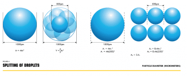
Figure 4: Splitting of droplets
using compressed air to forcefully push air and water into a convergent-divergent venturi. This process creates a standing shock wave of 47k Hz, essentially a high-frequency sound wave. Air is accelerated beyond the speed of sound through the venturi creating shock waves, which pass into a resonator cavity and are reflected back to amplify the subsequent waves.
The result is an intense field of sonic energy focused between the nozzle body and the resonator cavity. The diagram below shows a cross section of the orifice and resonator cavity.
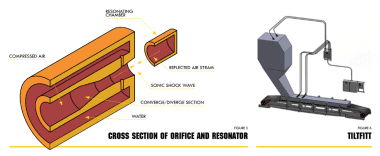
Figure 5: Cross section of orifice and resonator. Fig 6 Tiltfitt
The water particles are sheared by the incoming air down to smaller sized droplets and then enter the air stream. Upon entering the shock wave zone, the water droplets are shattered into very fine droplets below 10um in size. Due to the fact that the nozzle does not use high hydraulic pressure, the orifice opening for the water and air can be larger than normal atomization nozzles. Additionally, the sonic shock wave helps foster small vibrations that create a “self-cleaning” nozzle.
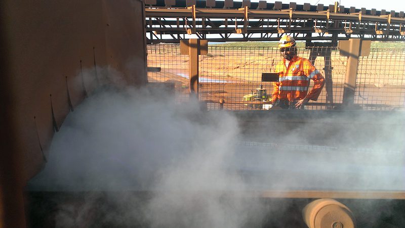
Dry Fog Dust Suppression Applications
A very common application for material movement in coal handling are transfer points. This is when the material is moved between conveyors which may or may not be moving in different directions. Dust is typically generated in two locations during material transfer. The first location is the discharge point where the material that is too light to fall during the discharge becomes airborne when moving from one conveyor to another. The second location and more significant area of dust creation is the receiving belt where the material lands. Typically, there is a skirt board, or what is commonly referred to as a conveyor cover, on the receiving belt.
To shield the dust particles that become airborne upon impact. However, due to the air movement from the displacement by the material, the dust that is generated moves with the material flow. This air displacement can be calculated by knowing the belt width, material bulk density, and material load (tons per hour). Air is created at a rate proportional to the belt width. The equation for this is as follows (source: Martin Engineering):
AG=350 x BW + AR
- AG= Air Generated
- BW = belt width in feet
- AR = Additional air generated from the drop.
If this is greater than a 3’ drop and BW is less than 3 than AR = 700. If there is a greater than 3’ drop and BW is greater than 3’ then AR = 1000. If the drop is less than 3’, then AR = 0
The displaced air is determined by tons per hour of the material and the material bulk density.
The equation is as follows:
AD = (K x L) / D
- AD = Displaced Air
- K = conversion factor 33.3
- D = Material bulk density (lbs/ft3)
Adding these two numbers together provides the amount of air flow through the transfer point. Higher numbers signify that more dry fog that would be required to agglomerate with
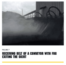
Figure 7: Receiving belt of a conveyor with fog exiting the skirt
the dust particles before they exit the conveyor cover. More nozzles are typically used at the impact point on the receiving conveyor due to the larger amount of dust generated at the impact on the receiving conveyor, more nozzles are typically used at that location to prevent the dust from exiting the conveyor into the open air (see Figure 7).
ROM Bins and Receiving Hoppers – dry fog applications
Another common dry fog application for coal handling is ROM bins and receiving hoppers, where coal is dumped by truck into a ROM bin at a mine, or transferred into a surge or receiving hopper. During this dumping process and when the material strikes the hopper below, the air is displaced and large plumes of dust rise out of the hopper.
Dry fog can be used to counteract the dust by creating a “blanket” of fog in the bin area, which captures the dust as it pushes up the walls of the
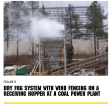
Figure 8: Photo of a dry fog system with wind fencing on a receiving hopper at a coal power plant.
bin, settling the dust back into the bin and preventing it from escaping to the atmosphere. As fog is light, it will also follow the uprush of air up the bin walls, and continues to act on any dust that may push through this blanket.
Where the ROM bin or hopper is exposed, dry fog can be used in conjunction with wind fencing to suppress this dust. The wind fence is used to contain the dust and dry fog in the same area to allow the agglomeration to occur between the dust particles and the fog droplets.
Additionally, the wind fence is used to reduce the speed of the wind that could potentially blow the dust or dry fog out of the area.
Train Unloading – dry fog dust control
Coal may arrive at an export terminal by rail. In the case where the material arrives via train, this is another potential area for dust creation. There are two types of coal unloading methods from railcars: rollover wagon tippler or belly dump. The wagon tippler is a process where a drive mechanism rotates the entire railcar onto its side and the material empties out of the top into hoppers below. This creates a large displacement of air and as the material hits the hoppers below causing the dust to rise with the air flow out of the hoppers. In a belly dump system, the bottom of the railcar opens to drop the materials into a hopper below. This operation also has the potential to create significant amounts of dust.
The wagon tippler creates more dust than a belly dump, however, both involve the same design concept. The idea is to use the sides of the hopper to the advantage of the dry fog. The hoppers are filled with fog prior to discharging the material to create a “blanket” across the open area, similar to with ROM bins and hoppers. When the material is discharged, the fog agglomerates with the dust prior to leaving the hopper, increasing the particle weight and returning it to the process. The air that flows out of the hopper will carry the additional fog.
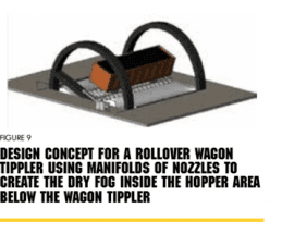
Figure 9: Design concept for a rollover wagon tippler using manifolds of nozzles to create the dry fog inside the hopper area below the wagon tippler.
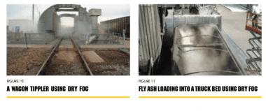
Figure 10: A wagon tippler using dry fog. Figure 11: Fly ash loading into a truck bed using Dry Fog
Crushing Area -dry fog applications
The crushing area at a coal mine typically consists of rotary breakers and scalping screens, or a crushing circuit and a screening circuit, where the material enters into the crusher building and is sent into a screen. The screen determines the material that does not need to be crushed (fines) and the material that is too large and needs to be crushed further. These areas act like transfer points moving the coal from one conveyor to another and through the crusher. A study was conducted to determine the dust concentration in various locations in the crushing area before and after the use of a fogging system (Warrington, 1979). The following results were obtained:
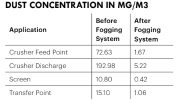
Application Before Fogging System After Fogging System Crusher Feed Point 72.63 1.67 Crusher Discharge 192.98 5.22 Screen 10.80 0.42 Transfer Point 15.10 1.06
There is an average reduction of almost 96% dust concentration in using the dry fog system within a crushing plant area.
Fly Ash Loading dust control
In coal power plants, fly ash is a by-product of the coal combustion process. The non- combustible minerals that occur from burning coal form bottom ash and fly ash. Bottom ash is a light-weight aggregate material that falls to the boiler bottom for collection. Fly ash are the fine particles of ash from solid fuel material that is carried off with the flue gases. The material is handled through conveying systems and then eventually loaded onto trucks which transport the fly ash to either a holding area at the plant or a storage area off-site. This product may also be recycled and used in other applications such as in cement plants. Fly ash has a very low material density, which makes it lightweight, fine and extremely dusty. The process of loading this onto trucks has the potential to create high levels of dust emissions.
Many plants use a pug mill or paddle mixer, which is a machine that adds water into the fly ash before it is loaded onto the trucks, however, this is detrimental to the process in that fly ash will harden when wet and moisture also adds weight to the process which adds costs during transportation. There are also operational and environmental factors when fly ash is converted from wet-to-dry. Dry systems offer plants the benefit of eliminating surface impoundments and their associated water quality and structural integrity risks.
Dry fog is one solution for the conveyance of bottom and fly ash that will not wet the product and can be used at the loading point. The system is designed to fill the truck bed with fog so that when the material impact causes a dust plume in the truck bed, the dust particles will agglomerate with the “blanket” of fog that covers the area. Dry fog can effectively suppress dust while adding less than 0.1% moisture to the process.
Wind Breaks for Fugitive Dust Abatement
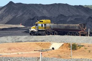
Open stockpiles are one of the largest sources of fugitive dust emissions (PM10 and PM2.5) in bulk material handling operations. Stockpiles, in addition to tailings, are found at mines, coal-fired electric generating plants, mineral processing plants and can contain any type of material including, but not limited to coal, clinker, cement, aggregate, asphalt, sulfur, or limestone. Most often, the piles are left open and exposed to weather, particularly if it is an active pile. Dust from stockpiles can be generated at several points through the process, including during material loading onto the pile, through erosion by wind currents, during loadout of the pile, and because of the movement of equipment and trucks in the area.
Dust from storage piles has the potential to have far-reaching effects based on wind speed, wind turbulence, and the particulate size and density. Wind erosion causes an estimated 30% of storage-pile fugitive dust emissions (Cowherd et al., 1974) and creates what is referred to as “particle uptake.” Particle uptake occurs when wind force builds up enough pressure on a pile that the material is lifted from the pile and becomes airborne.
Over the years, companies have used various techniques to reduce the effect of wind on the tockpiles and generation of the fugitive dust. Some of these methods are water sprays, chemical encrusting agents, fogging cannons, and full enclosure of the stockpiles. Full enclosure of stockpiles is typically not economical for the operator and would impact the operation of the plant. In regards to wetting, some materials are highly moisture sensitive and water sprays and chemicals are not preferable.
The concept of natural windbreaks has been in use for many years. Vegetative cover, commonly used by agricultural facilities, is an effective and easy way to control wind erosion, however it requires significant maintenance. Artificial windbreaks were modeled after this idea to create a surface barrier that deflects a sufficient amount of the wind force to lower wind velocities to the leeward below the threshold to initiate particle movement from the pile (Billman et. al 1984). Wind fences are constructed of engineered fabrics that are stronger and less susceptible to damage from storms or maintenance.
Wind Fence Design
The concept behind how a wind fence works is easy to understand. If a solid wall is used as a wind break, two different pressure zones are created as wind movement towards the wall increases. Because impermeable materials, such as a solid wall, only deflect wind, not reduce it, any openings for equipment access or areas on either side of the wall can funnel high pressure ambient air into the low pressure interior. This results in increased air velocities within the protected area. This will also cause wind to flow over the wall and create a turbulent movement on the other side, amplifying the wind speed and creating more particle uptake.
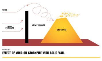
Figure 13a: Effect of wind on stockpile with solid wall
Conversely, if a porous material is used, high-velocity wind that moves toward the stockpile will be diminished as the porosity will allow for air to pass through and equalize differential pressure on either side of the barrier.
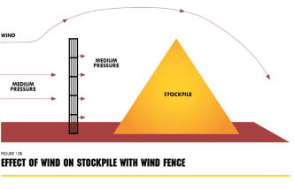
Figure 13b: Effect of wind on stockpile with wind fence
Below is an image showing this concept in a modelled design. It clearly shows how the wind fence reduces the wind speed beyond the fence while keeping the full speed wind at the height of the fence.
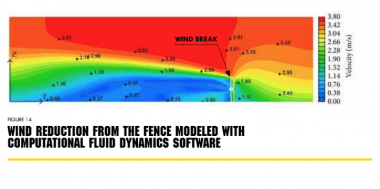 Figure 14: Wind reduction from the fence modelled with computational fluid dynamics software.
Using Wind Breaks for Fugitive Dust Reduction
The primary purpose of a wind fence is to reduce wind velocity moving towards the storage pile and prevent particle uptake in the protection zone. Particle uptake occurs when the wind speed is above a threshold velocity, which is determined by the type of stored material, moisture content, and the specific gravity of the dust particles. Once this threshold velocity is reached, particle movement can take place in three different ways: rolling, saltation, or suspension.
Wind break
- Rolling / Creep: Rolling and sliding movement of larger particles along the ground. Depending on wind velocity, material can be moved to another pile.
- Saltation: Movement of particles by a series of short bounces along the ground which also dislodges additional particles with each impact.
- Suspension: Fine particles move parallel to the surface and upward into the atmosphere by strong winds. Particles can be carried high into the atmosphere, only returning to earth when the wind subsides or they are carried down with precipitation. Suspended particles can potentially travel hundreds of miles.
Through various studies in the 1970’s it was determined that the threshold velocity for a coal stockpile with high fines ranges from 0.2 m/s to 2.0 m/s. Furthermore, other studies determined that 10 m/s could be a threshold velocity for certain stockpiles with larger material. The conclusion of the various studies corroborated that variables such as the type of material, particle size, and moisture content are all factors that contribute to particle uptake.
The true efficiency of a wind break is defined by the following equation:
E = 1 – (Q/Qo), where E is the efficiency, Q is the fugitive dust emission rate without the wind fence and Qo is the fugitive dust emission rate with the wind fence. This dust emission rate is again determined by the particle uptake, which can also be affected by the shape of the pile.
Wind Fence Applications
The following pictures provide representative samples of how wind fence material has successfully  diminished wind speed and provided a protection zone to material stockpiles and plant equipment.
IMAGES Wind fence surrounding gypsum stockpile, Start of wind fence installation around coal stockpile, Wind fence material providing protection from wind zone to rail car unloading area as well as an enclosure for dry fog system. Wind fence installation with steel beams, Wind fence installation with wood beams at coal mine
References:
Billman, B. and Arya, S.P.S. 1984. Windbreak Effectiveness for the Control of Fugitive Dust Emissions from Storage Piles: A Wind Tunnel Study. CR-811973. Atmosphere Sciences Research Laboratory, U.S. Environmental Protection Agency, Research Triangle Park, NC.
Colinet, J., Rider, J. et al. 2010. Best Practices for Dust Control in Coal Mining. Information Circuluar 9517. Department of Health and Human Services, Pittsburgh, PA USA.
Cowherd, C., Muleski, G., Kinsey, J. 1988. Control of Open Fugitive Dust Sources. EPA- 450/3-38-008. U.S. Environmental Protection Agency, Research Triangle Park, NC.
Daugherty, D.P and Coy, D.W. 1979. Assessment of the Use of Fugitive Dust Emission Control Devices. EPA-600/7-79-045. Research Triangle Institute. U.S. Environmental Protection Agency, Research Triangle Park, NC.
Douglas, P.L., Dullien F, Spink, D.R. 1976. An Investigation of the Operating Parameters of a Low Energy Wet Scrubber for Fine Particles. Canadian Journal of Chemical Engineering. Canadian Society of Chemical Engineering.
Hoenig, Stuart A. 1977. The Use of Electrostatically Charged Fog for Control of Dust from Open Sources. EP-600/7-77-131. U.S. Environmental Protection Agency, Research Triangle Park, NC.
Loredo-Souza, A, Schettini, E. S., Park, C. Paper #1161. Wind Tunnel Studies on the Shelter Effect of Porous Fences on Coal Pile Models of the CVRD – Vitoria, Brazil.
Schowengerdt, F.D., Brown, J.T., 1976. Colorado School of Mines Tackles Control of Spirable Coal Dust, Coal Age. Journal Volume: 81:4. Golden Colorado.
Warrington, Glen. 1979. Using Agglomerative Dust Suppression for Dust Abatement in Crushing and Screen Plants. Aggregate Producers Association of Ontario. Ottowa, Ontario. CA.
Coal Workers’ Pneumoconiosis Select Committee, May 2017. ‘Black Lung – White Lies’, Inquiry into the re-identification of Coal Workers Pneumoconiosis in Queensland: Executive Summary, Report No.52, 55th Parliamentary Enquiry.
Online Source – Vito Equations https://www.martin- eng.com/sites/default/files/downloadable-files/resourceswhite-papers/facts-concerning-dust- air.pdf
All project photos courtesy of Dust Solutions, Inc. Beaufort, SC. USA.
This paper was prepared by the following authors by AMSJ. The article also appears in the summer edition of Australasian Mine Safety Journal
Richard Posner, Dust Solutions, Inc.
Aura Poulsen, Dust Solutions, Inc.
David McMillan, MARC Technologies Pty Ltd.


Add Comment